What's new
Pinball info

Register a free account today to become a member! Once signed in, you'll be able to participate on this site by adding your own topics and posts, as well as connect with other members through your own private inbox!

Momentary Solenoids Dead on Bally GOLD BALL

Nedreud

Registered
10 Years
Joined
Feb 12, 2013
Messages
3,092
Location
Aldershot, UK
Finally managed to clear some space in my summerhouse/office/mancave/pinshack yesterday and fire up GOLD BALL ready for NPL in a forthnight. Oh dear... :confused: all the momentary solenoids are dead. That's 3 pop bumpers, 1 slingshot, 2 outhole kickers (normal and gold ball) and 1 knocker. All the continuous solenoids are working though (coin lock, flipper relay and the 2 coils that open and close the gold ball gate).

GOLD BALL uses the unique AS-2518-147 HV / LAMP / SOLENOID DRIVER COMBO board that was only used in GB and GRAND SLAM. It's saves 1 board in the backbox but has less circuits for lamps and solenoids, although it has a clever dual-phase system that uses the frequency of the AC supply to power 2 items per channel 180 degrees out of phase.
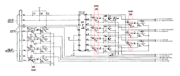
GOLDBALLCOMBO.png

Looking at the above schematic I can see that the data from the MPU comes in on connector J4. The data on lines PB4 to PB7 is for the continuous solenoids (working fine) and the data on PB0 to PB2 plus the BANK SELECT on CB2 controls the momentary solenoids. The fact the continuous solenoids are being controlled just fine would indicate that the MPU is at least sending the correct data on these inputs (I will need to put the oscilloscope on there to be sure, but let's assume PB0/1/2+CB2 are sending the correct control signals).

The momentary data then continues on to U3, a 74LS138 1-OF-8 DECODER. This takes the 3 bits and bank select signal and decodes it to enable one of the eight outputs. These in turn control the transistors in the U5 CA3081 NPN array which switch the SCRs providing a ground path to fire the relevant solenoid. All the output pins 9 to 15 read 3.6V with no change. That seems a bit odd. I do seem a momentary voltage drop on the diodes but it's only fractions of a volt.

Any ideas? At this stage I'm assuming U3 74LS138 is chuffed? Ordered a new one as only £1.75 posted from eBay. Hope it's not U5 CA3081 as they seem to be much more expensive with some sellers asking up to £20!
 
This happens on my GOLD BALL sometimes and a reseat connector cures it.
 
Just put the oscilloscope on U3. Data going in... nothing coming out. I monitored the input and output to U4 so I knew what to look for on U5, but whereas there was an obvious voltage drop on the base of the U4 transistors, e.g., on Pin 16 when the flipper enable relay clicks, there was no such change on the outputs of U5.

Current assumption still remains that U3, the 74LS138 1-of-8 decoder is furked.
 
Hi, Peter,

Do the three PB lines do anything else for the game, and if so, is that area okay?

I take it that Bally's cost saving meant there isn't a dedicated 'pre driver base probe' test point, as on the original Bally/Stern Sdu boards? (TP 7). You could improvise using a 1.2 K resistor to pull-up each input in the 3081 array chips, though..
 
Last edited:
Hi,

Do the three PB lines do anything else for the game, and if so, is that area okay?

I take it that bally's cost saving meant there isn't a dedicated 'pre driver base probe' test point, as on some Stern Sdu boards?. You could use a 3.9 K resistor to pull-up each input in the 3081 array chips, though..
Yes, PB0/1/2/3 are the 4-bit data to the sound card, which is working in test mode.
 
Pulled a 74LS138 from another (condition unknown) combo board I had and fitted it into new turned-pin socket. Still no joy. Not conclusive because I've no idea if it's working either.

Another quick test: all coils work if I momentarily connect the metal tab of each "Q" transistor to ground, so we definitely have power to all coils (and the solenoid ground return lines from the combo board back to the power supply are sound too).

So it's still most likely the U3 (74LS138), and then possibly U5 (CA3081).
 
Does U3 have power (and earth) to it? Have you reseated J4 half a dozen times? have you reflowed J4 connector?
 
Peter,

I was rushed when writing my original reply yesterday (90 seconds remaining), but the solenoid drive circuits aren't any different from the 'regular' Sdu board. So the 3081 Pre-driver array chip could be tried out by applying a simulated decoder pulse to each of the seven transistor bases in turn. The schematic doesn't show a test point for doing this, which was provided on the original design as TP 7. A 1.2k resistor connected the test point to the 5v line.
 
Does that game have a sol expander board on it ?
If it. Does ,in lamp test does it click ?
No solenoid expander board. GOLD BALL is as simple as it gets on a Bally! This was when things started to go downhill for Bally and they started cost cutting.

Everything on the game works. In test mode, all lamps flash, all displays work, all sounds work. When cycling through the solenoids all the continuous ones work. In game mode all switches work etc.

I just did a new test which is to ground the output pins 9 to 15 of U3 (74LS138 1-of-8 decoder). This simulates what the chip should be doing when it's supposed to be decoding the data on the address lines A0, A1 and A2 (pins 1, 2, and 3). All 7 momentary solenoids fired which means that chip U5 (CA3081 NPN array) is working.
 
Have you reseated J4 half a dozen times? have you reflowed J4 connector?
I'm enjoying this level of detailed t/shooting, but are you sure this connector is 100%? This is the one that I referred to earlier that I have to reseat occasionally on my GOLD BALL when the solenoids stop working. Perhaps some of your intermediate probing has discounted a problem in this area, if so ignore me and borrow my PCB :thumbs:
 
Does U3 have power (and earth) to it? Have you reseated J4 half a dozen times? have you reflowed J4 connector?
Power (pin 16) and ground (pin 8) are both good on U3. Have reseated all connectors several times! I haven't reflowed J4.

But... I did just put the scope on all the data lines again and guess what? The BANK SELECT CB2 wasn't getting from J5 Pin 5 to the input Pin 4 on U3! Dodgy connection in the IDC header :mad: I hate IDC headers. They're crap. Will replace with proper crimped and soldered Molex pins.
 
But... I did put the original 74LS138 back in (easy because I put in a chip socket) and it was FOOKED anyway!

And now we move on to the next problem... the slingshot has got about as much oomph as a soggy tissue! The plunger is binding somehow but it's not an obvious stick. It's already had a new coil sleeve and the plunger polished. It's one of the newer "linear" style slingshots instead of the earlier and more widely used "bell-crank" ones. Pull that out next and fettle. The SCR might be a bit crappy too. Got plenty of those spare! And need to do something with the lights in the 1-2-3 bonus spots. Think I might have left a crappy yellow LED in there and it's really hard to tell if 1 and 3 are lit. And I need to polish the playfield protector to make it super shiny!
 
That's good to hear, with the price of that simple chip nowadays.
Yeah, I was dead surprised. I thought I'd grab a couple of both 74LS138 and CA3081 from eBay, expecting them to be £1 or £2 each, but the CA3081 must be getting like hen's teeth if going for £10-20. There's probably a better equivalent, it's only an NPN array.
 
And now we move on to the next problem... the slingshot has got about as much oomph as a soggy tissue! The plunger is binding somehow but it's not an obvious stick. It's already had a new coil sleeve and the plunger polished. It's one of the newer "linear" style slingshots instead of the earlier and more widely used "bell-crank" ones.

Could just be an alignment problem, just slightly loosen the coil holder, end stop and anything else that may affect the alignment and see if the problem goes away then re-tighten.
 
Back
Top Bottom